Key Summary
• IPC’s milaero design course gives designers advanced skills beyond standard high-rel boards
• Instructor Kris Moyer provides deep manufacturing, assembly, and design theory
• Training helped Meijing master Altium and expand client opportunities
• Course covers vibration, stackups, DFM, and modern PCB process updates
• Education pipeline remains critical as veteran designers retire
This interview was previously published in MilAero007.
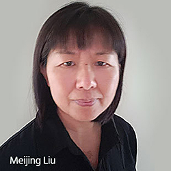
Meijing Liu, CID+, is a senior PCB designer for Microart Services, an EMS company in Markham, Ontario, Canada. She recently took a six-week milaero PCB design class from IPC’s Kris Moyer, and she was surprised at how much content she was able to absorb in such a short time. I spoke with Meijing and we discussed some of her takeaways from the class, and how it has inspired her to pursue more design education in the future.
Andy Shaughnessy: Meijing, tell me a little bit about your background. How did you get into electronics and PCB design?
Meijing Liu: My educational background is in engineering. I have a degree in electronics engineering. I worked in China for more than five years as an engineer. But after I came to Canada, there were no opportunities for me as an engineer.
Then I found this job at Microart through the help of a work placement program. I started working here, and now I’ve been at Microart for more than 20 years doing PCB design. I always focused on PCB design, and I really like designing boards. The company started out as a design house, but now we offer a lot of assembly services too. Design is an art, which I think is why they named the company Microart.
Shaughnessy: What do you like about designing boards?
Liu: It’s interesting, and as I said, PCB design is art. Also, it’s almost like a puzzle. With the same schematic and mechanical drawing, 100 designers can create 100 different designs, and the designs will act differently. I always try to find the best fit for each design with all of the considerations, like DFM, DFA, DFT, signal integrity and power integrity. You start with a schematic, and it’s up to you to make it all work. But if you just connect things, you can create a lot of noise.
Shaughnessy: Now, you recently took PCB Design for Military and Aerospace Applications, an advanced design class presented by Kris Moyer with IPC. Tell me about the class.
Liu: Kris was very inspirational. He explains everything clearly, and he really has a lot of design knowledge. Kris can always go deeper. The class I took focused on designing for military and aerospace, but it’s not limited to just that. What we learned in that class can be used everywhere. Kris also covered manufacturing and assembly, and that really refreshed my memory. I know how to do design and do it well, but sometimes I think I lack the theory that I need. Kris was fun, too.
Another reason why I enjoyed his class: Kris taught me how to use Altium Designer. IPC provided Altium software, but I’d never used it. In the past, I’ve mainly used OrCAD and PADS. I tried to master it and do my homework, but I had a lot of questions. I didn’t have the time to go through all the menus in such a short time. I sent Kris all of my questions, and he booked an extra hour to go through my questions with me. Kris also answered students’ questions before and after class. He helped me learn Altium and I really appreciate it. I not only learned a lot about designing military and aerospace boards, but he also taught me Altium. I use it all the time now. I had one longtime customer who switched to Altium last September, and I couldn't do their designs at the time. But after I learned Altium from this class, I reached out to my customer and started working with them right away.
Shaughnessy: What parts of this class really stood out for you?
Liu: We learned so much that it’s difficult to say. I took about 210 pages of notes. We spent a lot of time talking about designing for acceleration and high-frequency vibration, and tips for designing the best stackup when vibration is an issue. I also updated my knowledge regarding copper thieving. Much like etchback and inner layer copper balance, some companies may still list copper thieving as a design and manufacturing requirement, but with the latest PCB processes, copper thieving requirements are not necessary now. We focused on quite a few DFM concepts—simple things like mounting holes. But stackup is a big part of aerospace electronics.
The class was so inspiring. I learned so much that it made me start thinking about my career in the future. Now I’m a designer, but maybe later in life, I could work as a consultant and do more planning, and not just PCB design. I will probably take another class from Kris in the future. He’s a really good instructor. I learned a lot in his class.
Shaughnessy: Are you seeing more designers and design engineers coming into the industry? A lot of them are retiring, or they have their eye on retiring.
Liu: Yes, a lot of them retiring. Some of the new designers may have electronic engineering degrees, but they didn't learn PCB design in school, so they don't know the properties of the PCBs and how PCB properties affect the signals. They lack knowledge of the PCB manufacturing, assembly and testing processes. The older designers learned all of their knowledge through many years of work. Becoming a good designer requires dedication to learning in order to stay up to date with the latest technologies for PCB manufacturing and assembly. They don't really understand as much as the older designers. The new designers don’t know much about manufacturing, and they don’t realize that you have to dedicate yourself to learning and staying up to date with PCB design. A lot of young engineers don't understand design; they have good ideas, but they don’t really understand PCB design yet.
Shaughnessy: Well, it’s been great talking to you, Meijing.
Liu: Thank you, Andy! I enjoyed it.